Saturday, September 14, 2024

Short: Repairing a Sony ICF-2010 (ICF-2001D) radio

This is a radio that I probably didn't really need, but always wanted to have. Many decades ago I was doing a lot of DXing, with a Sony ICF7600 radio, which was sort of the smaller and much cheaper brother of the ICF-2001D (or by the US model number, the ICF-2010).

This model is an iconic portable receiver, due to not only its performace and features, but its part in a lot of interesting stories.


While browsing eBay, this specimen popped up, advertized as not powering up. I knew that this model had a problem with the battery holder for the 'computer' batteries. These are the batteries that power the digital part of the radio. They are required to be there to keep the time and the station memories. Without these batteries, the unit will not power up even when on mains! Many times people mistake this as some kind of grave problem, which results in a completely dead radio.
Anyway, the price was right, I took a chance and a couple of weeks later, after it did its travel across the Atlantic, I had it in my hands.

A wast amount of information, including scematics and service manual are available at the ICF20102001D usergroup.

A quick test confirmed my suspicion. The plastic post holding the battery terminal for the computer batteries was broken and was not making connection.


It was an easy fix with a bit of epoxy glue and the radio was operational. However, I did not want to stop here. There were a number of other problems. First of all, the radio was dirty. Second, the backligh was extremely weak, barely visible even in total darkness. Finally, the set was out of alignment, especially its main feature, the synchronous detector.

To clean it really well, the best was to completely disassemble the radio which made it possible to simply wash and scrub down the case. It is quite simple, the whole internals can be removed more or less in one large piece. The two main boards are fixed to an internal frame. There are some loose parts, and I had to be careful not to break the delicate wires going to the ferrite antenna coils.


The backlight replacement was a bit more involved. In theory it is a simple replacement of one LED. In practice however, the boards have to be removed from the frame, which includes unsoldering the rotary encoder fo the dial, removing some other jiggly bits and most importantly making sure to not damage the flex cables between the boards.

I opted to replace the faint green backlight with a high brightness golden yellow LED. I found it more pleasing to the eye. It is a simple round LED, once the set was apart, it was trivial to replace.

Realigning the receiver is not that easy though. The actual procedure is simple, but I need access to various parts of the radio, which not only includes connecting all the boards, but unsoldering shields, etc. I used my Agilent 6627A power supply to power the set. It needs 3V and 4.5V. This is how it looks why I'm operatig it disassembled. 

I performed the alignment steps and now I am a happy ower of one of the most iconic portable shortwave radios.


Thursday, December 7, 2023

Fluke 8860A repair

There was a Fluke 8860A benchtop multimeter on eBay, with a lot of red flags. It was not working, there was a tag on it saying that VR2 had been replaced, but it was still not working and the description said that it was unsuccessfully tinkered with to fix. It was also pretty dirty. All these turned out to be a good bargaining reasons and after some discussion with the seller I actually got it well below starting price.


Initial inspection did not show any visible damage, other than there were additional stickers discussing the VR2 repair. It was actually one of the regulators for the inguard 15V. 


After some sanity checks I powered it up and the only sign of life was the display showing 4 then changing to 8 and no response whatsoever. First check the power supply, especially with the VR2 issue.

The outguard power was good, but both the -15 and the +15V in-guard rails were nearly zero and the regulators were producing a lot of heat. Let's go for the usual suspects first. The usual suspects are the tantalum capacitors. I started removing the boards, and the +15V came back. But the -15 was still in short even with all boards removed. Looking at the schematics for the backplane, the culprit was easily found, one shorted tantalum. That fixed the -15.

The same troubleshooting method was used for the faulty board, I checked all tantalums with my Fluke 8842A, and high resolution resistance measurement quickly identified the other shorted cap.

Those were fixed, the power was OK, but still no operation. Since the display and the front panel are handled by the out-guard controller, I concentrated on that.

The CPU is an Intel 8039 microcontroller with external ROM and an Intel 8243 port expander. A quick check with the scope showed activity on the bus, there was no obvious stuck lines or shorts, the 74ls373 latch was working. Based on this I began to suspect software error, either because of bad ROM or some other problem with the memory selection. There is a ROM on the controller board, but there are additional ROMs on option cards, such as the GPIB board or the calculator board. There are some ID lines which are read by the CPU via the port expander and this way it knows which options are present. Then there are additional lines to activate the appropriate chip select line. The 8039 has a quite crazy memory banking architecture, to further complicate matters.

One interesting thing to note was that if I removed the GPIB board, then I got a different garbled screen, indicating that whatever was running in the controller, it was different. Since the GPIB board is optional, if everything is working then there should be no difference. So this clearly indicated that the software was bad, possible running partly from the optional ROM.

Now this could still be caused by a bad ROM on the controller as those ICs are known to be prone of bit-rot. But it could also be some problem with the chip selection, which is mostly done by lines from the port expander.

A logic analyzer would have helped, but I do not have one. So I chose an other path. I read the content of the ROM. Using a simple adapter, it could be read as a 2732 EPROM. I was trying to get a known good ROM image, but apparently nobody had it and it was nowhere to find on the net. I tried eevblog forums, ko4bb's site, Fluke mailing list and other places.

The ROM dump did not have any obvious problems, like stuck data bit (this was already verified with a scope) or stuck address bit. But I could not be sure of random errors. So what I did was to load the image into Ghidra and disassemble it. While Ghidra has some problems with the 8039 memory bank selection, I was still able to verify with a large certainty, that the ROM is ok. So I had to look elsewhere for the problem. The controller is quite simple, so basically there was nothing much left than the CPU and the port expander.

I figured that the CPU is more likely to be be ok, so I looked at the expander. It does quite a lot of


things including providing the chip select and additional address lines to the ROM. So a misbehaving expander could very well result in symptoms like this unit had. I was not absolutely sure, so initially I was contemplating to prepare an EPROM with special code to exercise the ports and check with an oscilloscope. But I decided to simply replace the expander, as is readily available on eBay, from reputable sellers for only a couple of dollars. I removed the old one, soldered in a socket just in case and plugged in the new port expander.


Indeed this was the problem, the 8860A sprung to life and a quick check had shown that all modes were working and the measurements were good. I did upload the ROM image to KO4BB's site, to help others.

So bit of a debugging, thinking and some luck resulted in a nice vintage 5.5 digit Fluke benchtop meter. Which I don't really need, but hey, one can never have enough multimeter, right?


Thursday, November 9, 2023

Repairing an HP 5334B counter and adding the C channel option

While browsing eBay, I came across an HP5334B counter. I already have one, so I don't need another, especially that this one was without opt 003, which is the 1.3GHz C channel. However, this was advertised for cheap, with the comment that it was working until a bang with smoke. This pretty much point to some Rifa capacitor self destruction, thus a low hanging fruit for repair and resell.  Fortunately nobody else wanted the one on eBay, so I got it for the starting price. Unfortunately devices without C channel don't sell for much but I had an idea.

While repairing my other 5334B I acquired a complete front panel while looking for the plastic filter in front of the display. This panel was complete with the proper hole and legends for channel C. The fused BNC connector was damaged, but that could be replaced (more on this later).

So I had a 5334B without channel C, and a font panel with Channel C. The perfect combination to create a working instrument with opt 003 for sale.

First checks indicated a blown main fuse. The reason: Rifa caps. The X cap was shorted.  

I replaced the capacitor and the fuse. Plugged it in and it stared up with the standby led on. Nice. Switched it on it worked for maybe five seconds, then a mighty bang, sparks and blown fuse. What the heck???


Nothing surprising, a tantalum capacitor has exploded, it was literary blown into several pieces. So I replaced that capacitor and the fuse again and since then everything has been working well. 

The next step is retrofitting channel C. It has already been done before, there is an excellent write-up on this. I loosely followed this description.

So what is needed? The 5334B is quite interesting, it seems like channel C became an option at the last moment during the design of this counter. Most of the electronics are already there in the base instrument. The only parts that are missing is the Fujitsu MB506 prescaler IC. It even has a socket, so just needs to be plugged in. The only thing to look out here is to NOT buy a fake IC from eBay.
Besides that two diode bridges need to be soldered in for the peak detector and the limiter. The original diodes are HP 5082-2831. They are still available, but costly and simple to replace with SMD Schottky diodes. Those can be soldered in with a steady hand and a thin soldering iron.

The final component for the C channel is the most difficult if one wants a identical to original retrofit. It is certainly possible to drill a hole on the front and just install a BNC connector, but it would not look original at all. It's not only the connector, but for example the Freq C text is also missing from the appropriate button.

This is where I was lucky. As I mentioned I had a spare front panel, which only needed a new fused BNC. After some research and help from the HP mailing list I figured out the part number. It is an M/A COM 3284-3201-10, panel mount BNC to SMC connector. It is an obsolete part, but seems to be available in abundance on eBay. It also needs an SMC pigtail, which is simple. 


Here is the photo of the whole setup. The SMC pigtail is plugged into the connector and solered to the main board. The four diodes are soldered into their place and finally the prescaler is inserted into the socket.

That is it, we now have an operational channel C. The only required adjustment is to set the peak detector so without input signal there is no counting. The prescaler is oscillating with no input, so HP put in the peak detector to actually only allow counting when there is a real input signal.

As usual for the conservative specifications, HP specs channel C to 1.3GHz. In reality it is happily working over 2 GHz.
The only open question now is what to do with an other 5334B.


Thursday, April 13, 2023

Short: Hacking an external battery onto the Dallas DS1235 nvram

I was repairing a Tektronix 2430 digital oscilloscope. It had power supply issues, which I won't describe here, it just needed new electrolytic capacitors, as usual.

However, it was also forgetting calibration*, which pointed to the DS1235 nvram's internal battery being discharged. It was not hard to diagnose, especially that the scope was failing the nvram battery test.

The problem with this and the similar Dallas nvrams is that they have a built in battery, meaning that the lithium cell is attached to the ram circuit and the whole thing is potted into one sealed case. Sometimes these can work for decades, depending on for how much time the instrument is powered up, because then the ram is using external power. But, sooner or later all of them will become discharged. Unfortunately many of these types of components are obsolete, and there are a lot of fake ones on eBay, so it can be hard to find a replacement. There are workarounds by replacing them with other types of nvram devices, such as frams, but what I want to show here is how to attach an external battery. This is not new, there are several tutorials for doing it for various devices, but AFAIK this method has not been shown for the specifically the DS1235.

This nvram has two batteries and a DS1210 nvram controller chip, which is actually visible on the bottom. Also visible are the outlines of the battery, The goal is to remove at least one of the batteries and connect an external battery there. The DS1210 will automatically select the battery with the higher voltage, so it is sufficient to use only one battery.

The way I achieved it was by heating the potting compaoud with a heat gun which made it rubbery and it was easy to dig out the batter. Do not heat so much that the baterry explodes! Make a hole into the button cell, if you are afraid of explosion.


Once the battery is removed, it is simple from here. Solder some wires and a battery holder. I used a CR2032 cell. I used a dab of epoxy to fasten the wires.


I should have used a shorter piece of wire, but originally I wnated to put the battery holders to the side of the PCB. However, I realized that there is room on the top of the nvrams, so again epoxy came to help. Some Kapton tape was used to provent the case accidentally shorting.Not a winner of a beauty contest, but works.


 *In many cases people go great lengths to save calibration data from these nvrams. In the case of the Tektronix 24xx series Digital Scopes (2430, 2432, 2444) it is completely unneccesary. The scope is cabaple of nearly automatic self-calibration. Some external signals need to be provided in the form of DC levels and square waves, but these are easily obtainable. So don't save the nvram data, simply redo the calibration. That should be done periodically anyway. This is not the case with the 24xx series analog scopes like the 2445, 2465 etc. Their calibration is a tedious process and requires some quite spocialized equipment. Still it doesn't hurt to do it peridically, especially after repairs.

Saturday, March 11, 2023

Restoring a 90 years old portable radio

I was recently given a Vatea Touring radio. One interesting thing about this set is that it was manufactured between 1929 and 1932. So it makes it at least 90 years old.  I was unable to determine the exact vintage of this set, the serial number stamped into the wood was unreadable.

Vatea was a Hungarian manufacturer of vacuum tubes, later absorbed into Philips. As far as it is known the Touring was the only radio set manufactured by them. Most likely it was actually contracted to some other company, but very little information survived about it. There are a number of Tourings in existence, but it is still a quite rare object.

 The other interesting thing is that this is a portable radio (hence the name Touring). It uses a 1.5V battery for filament heater and four 4.5V lantern battery for anode. There are connectors for external power supply, including the optional grid bias voltage for the amplifier tube. It uses 2 DX106 space charge tubes, which makes it possible to use a relatively low plate voltage.

One tube works as a regenerative receiver and the other as the amplifier, providing enough amplification to drive a pair of headphones. The built in aerial is a loop type built around the edge of the case and it also serves as the coil in the tuning circuit. The feedback coil is built the same way. There is a jack for external aerial too.

There is a coupling AF transformer between the detector and the amplifier and basically that is all. There is nothing exceptionally special in the schematics of the radio.

To properly make decisions about the restoration I had to examine the current state of the set. As there are little information available, I asked for photos of similar sets owned by fellow collectors.


These were the main issues:

  • The wooden case was cracked and warped, the front panel was half detached from the frame.
  • The radio was full of dirt and dust.
  • Both variable capacitors were stuck.
  • The connectors for the anode batteries were missing.
  • The screw terminal for the filament negative was missing.
  • All battery connections were implemented with dangling leads. The insulation was brittle and flaking on these wires.
  • Most of the original internal wiring was replaced, the wire to the -optional- grid bias socket was missing.
  • The tuning capacitor was not original.
  • The coupling transformer was not original.
  • The audion tube socket was relocated a bit, I have found the original screw holes.  

They seem a lot, but in fact for a radio of this age, it is quite ok. Even though it had been rebuilt at some point of time, most of the important parts were there. So the real decision for me was whether to restore it to the most original state possible or leave it as is and just fix the serious issues.

My decision was to rebuild. It has already underwent a lot of change, so it cannot be considered original. I do not see any problem in a repair that takes it closer to the original state. Since the case was cracked I needed to remove everything from the inside for the repair. That also gave an excellent opportunity to clean all the components.

Once the internals were removed I cleaned the case and glued it back together.

The stuck variable capacitors have been freed by using a little bit of penetrating oil on the shaft, then cleaning it. At that time I discovered that one of the dials had cracked due to the stress of the set screws that hold it to the capacitor's shaft. A bit of epoxy quickly solved this, with some glass fiber reinforcement at the back.

I opted for recreating the original wiring by using original looking thread insulated wires. All other componets have been reinstalled. Finally came the battery connectors. The anode battery connectors were missing, there were only holes in their place. I managed to find some copper thumbtacks that looked remarcably like the orginals. For the filament battery the screw terminal post was also missing, fortunately I found a replacement on eBay.

With everything in place, it was time to test. Using my newly fixed Agilent 6627A power supply I set the filament, anode and grid bias supply. The nice HP 8640B signal generator was supplying the RF, via the radio's external antenna connector. It was really cool to hear the old set woring, becasue it did work at first try!

The only thing left was to source four 4.5V lantern battery for anode voltage and a D cell for filament. The filament cell is coverd in a termporary cardboard envlosure on the pictire to the right. It is a future project to make a replica of the original battery. The 4.5V batteries are simply inserted in the slot with their tabs folded onto their side, thus connecting them in series for the 18V anode voltage. When working on battery power there is no grid bias, it is simply connected to ground with a shorting plug.

The large empty space next to them is a place for the headphones, unfortunaltey I do not have a headphone that fits there.

The radio works really well on batteries, I can receive loud and clear the two local stations on 540 and 873 kHz. There aren't that many stations than what used to be decades ago. But it is still nice to have a set in working condition that was manufactured about 90 years ago.


Wednesday, March 1, 2023

Short: fixing a rechargeable torch from Aldi

I have a quite powerful torch, which I bought a couple of year ago in Aldi. It is compact, yet provides very efficient illumination either as a beam or as a workplace illumination and has a magnetic stand.


I was using it and suddenly it ceased to work. No light and when trying to charge it indicated being nearly fully recharged, but never stopped charging. It was hanging around for a year or two, but finally I decided to take it apart and see what's up. It is surprisingly well built. Three screws need to be removed, as well as the front lens and the two blue panels need to be pried off. The side light and the main panel are also held in place by small screws. The whole inside can then be removed from the case.

The main parts are the battery, which includes a BMS module, the main board with the charging circuit and the light logic which operates the two separate lights and the intensity control. The push-button switch is on a separate board. Finally there are the LED modules for the front beam and the side work-light.

The battery measures 0V on the main board and very quickly I see a problem. One of the wires got pinched under one of the screw posts on the case and it seems to be broken. That is an easy fix. However, when I stripped the wire and measured voltage there, still 0V. OK, the battery may be discharged and the BMS module is shutting it off. I tried charging, but it would not take up any charge at all. I had to remove the shrink tube wrapping disconnect the BMS and charge the cell directly. It would still not respond to charging. So I'm in a strange situation that there is a broken wire and a dead cell at the same time. I don't think there is any connection (pun not intended) between them, but it might be that the cell died while being left discharged for a long time.

Since I really liked this torch, I carried on with the repair. The broken wire was reconnected and insulated with shrink tube. In the meantime I ordered a new 16850 cell with solder tabs. The BMS module got soldered to it and lacking proper size shrink tubing I wrapped it into kapton tape instead.


 That is it. Reassemble the whole thing and enjoy.


Tuesday, February 14, 2023

Short: RIFA fun

Everyone working on vintage test equipment knows these. The infamous RIFA caps.


Rifa was a Swedish electronic component manufacturer and their film capacitors were used in many test equipment as line filter X and Y capacitors. They are also notorious for becoming bad due to various effects and exploding when put under voltage.I'm not a fan of indiscriminate replacing capacitors ('recapping') in old equipment, but Rifas just have to go, they will explode nearly every time if not replaced.

Jerry Walker has an excellent video on the problem.


 He also has a comprehensive analysis of the problem.

Dave Jones of EEVblog also discusses the issue.


The Emperor of test Equipment list dozens of devices where the Rifas had to be replaced.
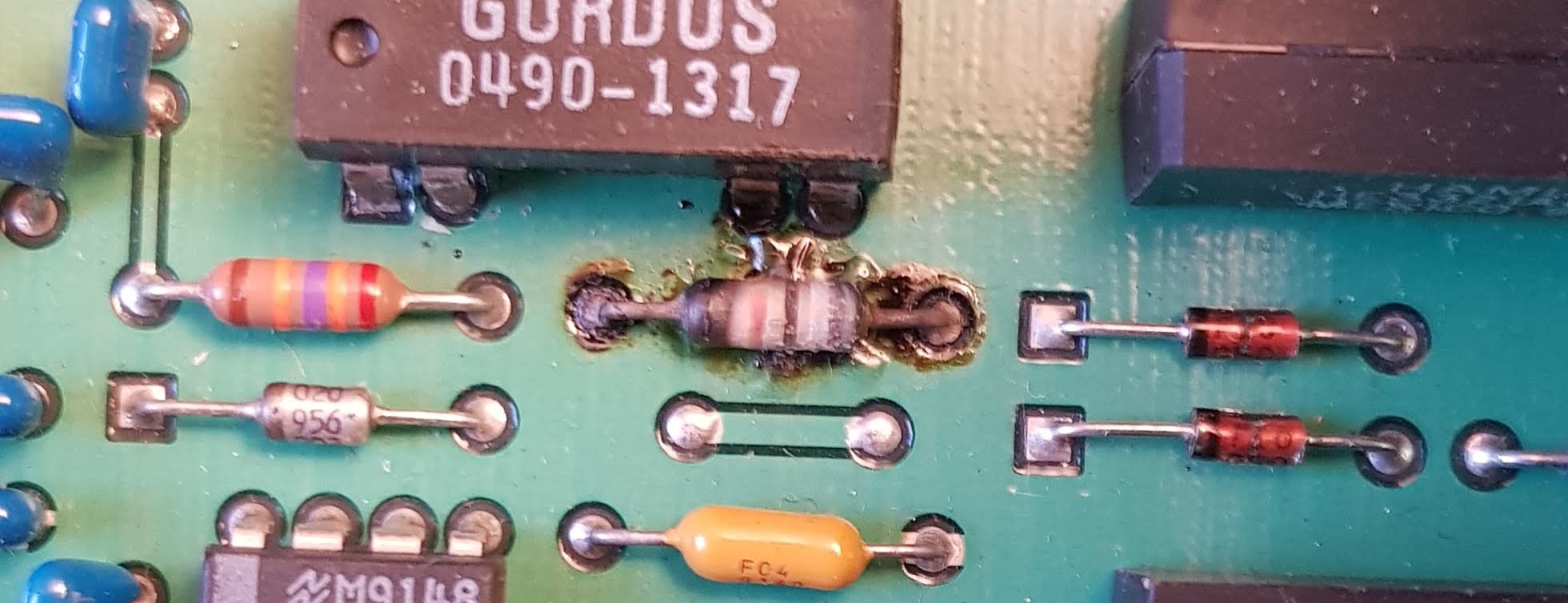
The list goes on and on, just search for Rifa capacitor failure. The takeaway from all this is if you see these suckers, replaced them without thinking, or face the consequences of the stinky mess when they explode.


Wednesday, February 8, 2023

Short: breakout box for the Agilent 6627A quad power supply

Since my 6627A quad power supply is working again, I finally decided to make something long overdue. A breakout box to be able to simply connect to supply to whatever I'm doing on my bench. This is not a complicated design, I had all the components lying around.

The basic function is very simple. The 6627A does not have front connectors, it is designed to be a system power supply sitting in a rack with other equipment. The box connects the rear panel terminal strip to binding posts in an organized manner, so that the supply can be left on the shelf, without the need to access its rear.

I had a buch of HP-like binding posts and also an unused good quality plastic box. I arranged the binding posts on the box in 2 rows of 2 four wire connectors. I used the four wire to be able to compensate for the voltage drop on the connecting cable by also having the sense terminals on the box.


For the wiring, I used two four wire cable for the 4 channels' voltage outputs and one cable with 4 twisted pair lines for the sense lines. The sense lines can be much less in cross section, as they do not carry high current, but they are recommended to be twisted pair for noise suppression.


The whole project took a couple of hours. I drilled the box for the binding posts and connected the wires with spade terminals at the end. Unfortunately the box is a bit small, more space between the channels would have been nice for access, but not a big deal.

The posts for each channel are the standard 19mm apart, so two or four prong connectors could be used.

Basically that is it. I can now put the box on the bench and have the power supply available there. Obviously, the voltage and the sense terminals have to be connected. They will likely be shorted at the box most of the time, but if required this connection can be made elsewhere.

I still need to put labels on the box to identify the channels. It is really bad if you accidentally mix up power supply channels.


Tuesday, February 7, 2023

Repairing an Agilent 6627A quad power supply - Part 2: wrapping up

In Part 1 I started working on the Agilent 6627A quad power supply with one bad channel. Replacing Q319 did not fix it, however there were changes. The -7 Volt rail was now low. Curiously this rail is called -5.75V on the schematics for the 1 and 3 power output boards, even though they are identical to the 2 and 4 boards, where it is correctly shown as -7. The circuits are the same only the PCBs are sort of mirrored so two of these boards can fit next to each other with the power modules facing the fan. I assume this is a mistake in the schematics, or maybe the remains of an older version. Anyway, I had to find out what pulled the voltage down (well, up, towards 0V).


Q319 was replaced so I traced which signal goes where. The circuit with Q319 has only one output-like signal, the BLEED_SINK line for the downprogrammer circuit. The only obvious fault which could pull the -7V down is a shorted CR355, which is a 1N4850 diode. A quick check proved that it was indeed shorted. The 1N4850 is a bit hard to find, but it should not be too different from the very common 1N4148, other than a lower voltage and a higher current. Actually the higher current requirement was inconclusive, as some datasheets gave the same current for both. Since the 1N4148 is higher voltage it should not matter at least for a trial. So I replaced CR355 with a 1N4148.

This still did not fix the power supply, but there was yet again some change. The output would now not stay at zero, but tried to output some voltage, then drop to 0 and start again. The supply was still alternating in CV, CC and UNREG modes. The -7V rail was still very low and pulsating as the output would try to regulate.

So it was time to look at what else could have caused this. Disconnecting R314 fusible resistor would unload the -7V supply, which could be now verified that it worked without load. I then scrutinized the schematics for all appearances of this power line, looking for possible sources of fault. CR352 and CR353 diodes were OK. The next suspect was the C370 tantalum. Tantalums are always suspect! It was a bit hard to get to it, as it is mostly covered by the heat-sink, but removing the board made access possible. Indeed this capacitor measured 5 ohms in both polarities, which is not good. I did not have replacement, so simply removed it, which should again be fine for testing. Once this capacitor was out, the power board came to life and provided rock solid output. C370 is not a filter cap across the power rail, so until the other problems were fixed it did not affected the -7V. Once the broken trace to Q319 was reconnected, this cap came into play. At the beginning of the troubleshooting the -7V power was in spec.

I ordered a new 1N4150 and a 39uF tantalum, they should be here in the coming days. But I consider the repair successful. I will still need to verify and if required calibrate the supply, but that should be simple.

There were 4 fault is the unit. A shorted transistor, a broken trace, a shorted diode and a shorted tantalum. The first 3 are in the same part of the circuit and their demise could be related, but I don't really see how the trace broke, as the -7V is current limited probably below damage levels. Maybe some external impact? The capacitor most likely became shorted by itself.

The moral of the story is that there could be several fault creating similar symptoms, never assume that replacing one faulty component should fix the problem. Actually fixing something might uncover other hitherto unknown problems. This means one needs to restart the troubleshooting and not think that if a power rail was good at the beginning it would stay so during the repair. 

Study the schematics and figure out which bad components could result in the observed fault. Go methodically and test them.


Sunday, January 22, 2023

Repair of an HP 5334B counter - Part 2 - finish

Back from a long break when I did not have much time to tinker with electronics stuff. But back with full steam, I picked the 5334B from the backlog to finish first.

I traced the signal path for channel A, and very quickly found that the Q8 jFET was dead. It is a 2N4416, which I was able to source easily. It was cheap, so I made sure that I buy more than one, which later proved to be a wise decision. After replacing it, channel A immediately sprung to life. So channel A is working.

But not finished yet. While channel B seemed to work on initial inspection, it had much reduced sensitivity and bad offset with the trigger level. This was more challenging to troubleshoot. The way the trigger level setting works is that there is a comparator (U22), which always compares at 0V. The input signal is given an offset, which will counterbalance the signal, so that the desired trigger point falls on the 0V level. Normally the trigger level is between -5V and 5V and thus the offset is from 5V to -5V. In reality the offset has other value, because of the gain on the input stage. The problem was that this offset only moved in the negative region, it would not go above around 0.7V.

I had to trace some signals. The trigger level from the front panel pots goes trough a number of analog switches in the DAC section. Fortunately, that was ok. I saw that the full range swing is present when it reaches the amplifier section. There however, something doesn't work. After some pondering and measuring voltages I was able to exclude most of the possibly bad components, with the exception of Q9, the same jFET that was bad in channel A. It was the last component that could have produced the fault and while I couldn't definitely say that it was bad, I had a spare and it was easier to replace than to do more measurements. This promptly fixed the fault!


So in both channels the jFET was bad! The one in channel A was completely dead and the one in channel B was sort of half bad, still enabling some level of functioning. The replacements are the ones with the number 138 on them on the above picture. Note the Teflon standoffs, they are used to provide more isolation to the gate.

Looking at R113, which was burned, I couldn't really figure out what happened. Since that resistor cannot really be overloaded by DC from the input, I suspect either some botched repair, like accidentally shorting something or maybe some brutal high frequency input overload. But I'm not able to tell why these components failed. 

Nevertheless, I performed the adjustment steps in the service manual, since the input stage had been  repaired. All steps completed correctly, so I'm happy to have yet another nice universal counter after a quite challenging repair. One can never have enough frequency counters!


Sunday, October 3, 2021

Repair of an HP 5334B counter - Part 1 - first looks

Some time ago, I got an HP 5334B counter off eBay. It was advertised az not powering up and it had a best offer option. I like not powering up stuff, as usually they have some simple problems. It was missing the display cover, but since the unit had the OCXO option and based on the pictures I was able to confirm that the HP 10811 oven oscillator was there, I submitted an offer of about the third of what the OCXO is worth by itself. Somewhat to my surprise the offer was accepted and the counter was on its way to me.


Initial inspection has shown that there were no major parts missing and it indeed had the oven oscillator.


After making sure on the line voltage setting, I also confirmed that it did not power up, not even the standby led, which should indicate that the oven is powered up. So I checked the trivial stuff first. The fuse seemed to be good, but I always measure if it does not look obviously blown.


Hmmmm. That OL on the meter is sure makes me suspicious that the fuse is not as good as it looks. I got a replacement and look, it powers up. That sure is easy. Or maybe not, still need to test it.


In case you are wondering in the meantime I was able to get a front panel for a couple of bucks, complete with the display cover. The cover was installed, it simply pops into place and I now have a bunch of replacement switches for vintage HP equipment. It also had the plastic trim on the upper side of the front, so test equipment OCD was avoided this time, by not missing anything from the unit.

However, not all is nice. The trigger led for channel A is always lit and channel A does not work at all. B and C do. Fortunately for someone who repairs test equipment for fun, it was not simply a blown fuse.

So let's get the service manual and follow the signal path for the input. In this case, the gameplan is to simply follow along and see where the signal disappears. The input may have been blown by overvoltage or anything like that could have happened, so a systematic fault finding is the best way to go.

Connecting A and B with the Com key will make Channel B count the A input, but that does not help a lot, since the Common switch as very near to the front of Channel A, only the AC/DC coupling switch (relay) and the 50 ohm input terminating resistor is there. But, at least we know that those are good.

On the other hand I discovered that R113 is fried. So there was very likely some overload situation.


The only problem is that R113 is in Channel B, so this is not the cause of a faulty Channel A.

In the next part I'll go trough the testing of Channel A components. 

Thursday, May 20, 2021

Repairing an Agilent 6627A quad power supply - Part 1

For some time I have an Agilent 6627A quad power supply, which had one bad channel (the reason I could get it for a good price). While so far I didn't really need it, it always bugged me to have faulty equipment.

The symptom is that the output is always at 0 Volts. The channel is in unregulated state, but otherwise there is no error, it passes self test. The self test mostly covers the digital part only, so this is not a surprise.

I have verified that the readback works by forcing voltage and current on the output. This supply can also sink current, so no harm in doing this.

The power supply has 3 main components. A huge (I mean huge!) transformer, as this is a linear supply. A control board + front panel and the channel boards. In this case it has 4 identical (nearly, as for packaging reasons they are 2 + 2 more or less symmetric boards. In other configuration there are less channels and there are double sized boards with double power. But the 6627A has 4 40W 0-50V output boards. This can greatly simplify debugging as there is a working reference.
The whole setup is in a quite clever fold out design, where the upper output boards fold out on a hinged aluminium plate.

The channel boards are quite complex, with their own microcontroller, DACs, ADCs, etc, so debugging is far from straightforward.

In this unit channel 1 is bad, which is the lower left board. After some visual inspection for anything suspicious I decided to swap this with channel 2, which is one of the upper boards. This would give better access and I wouldn't have to poke around the line input at the back. So I did that, quite easy, just had to remove 4 screws and a some connectors. Probably this will require re-calibration, but I would do that anyway later. 

For initial troubleshooting I went with the guide in the service manual, it has an extensive troubleshooting section. All voltages were ok, the DACs are ok, and the usual suspects were quickly eliminated. 

I finally reached Q319, a simple 2N2222A transistor which had a short. Replaced, but nothing happened. I realized that its emitter should be at -7V, but it was not.

There was no connection between the -7V regulator and Q319, so I began to trace the connection and saw that the the trace is burned up at one point, so clearly there was some catastrophic event.  Maybe it was caused by the shorted transistor or maybe the short happened as a result of something else. Anyway, it needs to be fixed to continue.

The trace broke where it passes between the two pins. The solution is to bridge this. Since it is at a very inconvenient place, I decided to use a jumper wire on the solder side instead.  

Fortunately there were two nearby vias, where i could attach the wire, so it was quickly fixed.

That fixed, the result is that the channel is now jumping between CV, CC and unreg modes and the -7V rail is down to about about -4V.
So obviously there are still things remaining to be fixed.

My approach is now to study the schematics in more detail to more deeply understand how it is working and trying to come up with what faults can cause these symptoms.

Stay tuned for the next part, while I continue finding the problem and writing Part 2 of this post.


Tuesday, April 20, 2021

Fixing an HP 3314A function generator - repair complete!

Wrapping up from Part 2

I managed to source a CA3082 locally, so there is no need for any workaround. I popped it in, and it worked.


I had a problem with one of the reed relays, but this time it was not on the driver side, but on the actual reed contact. It wouldn't work however I exercised it by quick switching. By luck, I had a handful of reed contacts with the same size, so I snipped the old one out, it was spot welded and soldered in the new one. Carefully, they are fragile. I say this from experience.

 Fortunately both leads could be soldered well, it would have been hard to weld them again. 

I went trough the adjustment section of the manual, got everything in spec. Now I have proudly resurrected a vintage 3314A from a quite bad repair attempt by a previous owner. 

It is a nice and still quite capable instrument.


Tuesday, April 13, 2021

Fixing an HP 3314A function generator - Part 2.

Continuing with the repair of the HP 3314A function generator that was "repaired" by a previous owner. I left off at the decision of checking everything that was done to it.

First I had to clean up. 5 of the 6 EPROM adapter boards were soldered into the instrument and for some unknown reason 1 was in a socket. I started beeping out the connection between the EPROMs for the data and address lines, and sure enough, found several where there were no connection. Not very surprising, given what I have seen with the 74S74 IC in the clock generator circuit. Also, some of the adapter boards were bad, there was no connection between some of the pins, there were cold solder joins there.

Very carefully I started removing the adapters. Even though HP made quite sturdy PCBs, I didn't want to risk any more damage, so I snipped the pins of the adapters and removed them one by one. I also removed the two 74ls373, they are the ones with the two jumpers next to them. You can see the solder blobs at their ends near to the EPROMs. That is where their pins were snipped and soldered from above, presumably to fit after the adapter boards were already put in.

Once everything was removed, I was already able to see four broken traces under U209, the one in the socket. Those were fixed with scraping off the solder mask and soldering twin wires there.

Then I checked for continuity for every pad related to the ROMs and installed high quality sockets and replaced the 2 74ls373. All this took quite some time, but was well worth the effort as at the end I had a nice board.

I again double checked continuity to the sockets and proceeded with getting the EPROMs fixed.

Next, I turned my attention to the adapter boards. My initial idea was to scrap the 6 EPROMs and just use one with a 74ls148 priority encoder figuring out the additional address lines from the 6 chip select signals. But to make it nice it needed some PCB, and work, and then I also realized I actually had 3 of the same (well, nearly same, they were blue, and a bit different layout) adapter boards from an earlier project, so I actually only had to clean up three of the old ones. So I went with tidying up those boards, as the previous owner even got those wrong, instead of using the proper jumper places he used bodge wires to configure it. After some tedious work with the solder sucker and the iron, I got all six EPROMs ready for action.

Plugged them in and did again a quick check that everything is in place and turned the instrument on. It started the countdown and then did the calibration sequence without problem. Honestly I wasn't expecting that, I was prepared to see a bunch of calibration errors at best.

Halleluja! But does it play Halleluja? No! There is no output. There is output from the sync, but nothing from the signal. 

Ok, don't panic, just think. If the calibration sequence is successful, then there must be a signal with proper amplitude and frequency where the calibration signal is picked off. Looking at the schematics, this is done nearly at the very end, after the output amplifier, but before the output attenuator.  I quickly verified this with a scope. Looks like the signal is lost somewhere at the reed relays. So the main suspect now is the relays themselves or the drivers of the relay coils.

The relays are controlled by a latch which in turn controls a CA3082 transistor array. The latch seems to be good, but the voltages on some of the outputs of the array were strange. As a quick test I piggybacked some random NPN transistor on one of these outputs, and surprise surprise, the corresponding relay came to life. 

So the CA3082 seems to be a fault. This is an obsolete part, not too easy to get. Of course I made a purchase on eBay for some cheap solution, I'm pretty much certain that it will be fake, but let's take some chances. As plan B I also designed a small PCB with surface mount transistors as a pin compatible replacement. 
So right now I'm waiting for either a working replacement or the PCB. This will take a couple of weeks probably. Hopefully this will fix the instrument. I'll write a Part 3. of this post once this happens.