Showing posts with label HP 5334B. Show all posts

Sunday, January 22, 2023

Repair of an HP 5334B counter - Part 2 - finish

Back from a long break when I did not have much time to tinker with electronics stuff. But back with full steam, I picked the 5334B from the backlog to finish first.

I traced the signal path for channel A, and very quickly found that the Q8 jFET was dead. It is a 2N4416, which I was able to source easily. It was cheap, so I made sure that I buy more than one, which later proved to be a wise decision. After replacing it, channel A immediately sprung to life. So channel A is working.

But not finished yet. While channel B seemed to work on initial inspection, it had much reduced sensitivity and bad offset with the trigger level. This was more challenging to troubleshoot. The way the trigger level setting works is that there is a comparator (U22), which always compares at 0V. The input signal is given an offset, which will counterbalance the signal, so that the desired trigger point falls on the 0V level. Normally the trigger level is between -5V and 5V and thus the offset is from 5V to -5V. In reality the offset has other value, because of the gain on the input stage. The problem was that this offset only moved in the negative region, it would not go above around 0.7V.

I had to trace some signals. The trigger level from the front panel pots goes trough a number of analog switches in the DAC section. Fortunately, that was ok. I saw that the full range swing is present when it reaches the amplifier section. There however, something doesn't work. After some pondering and measuring voltages I was able to exclude most of the possibly bad components, with the exception of Q9, the same jFET that was bad in channel A. It was the last component that could have produced the fault and while I couldn't definitely say that it was bad, I had a spare and it was easier to replace than to do more measurements. This promptly fixed the fault!


So in both channels the jFET was bad! The one in channel A was completely dead and the one in channel B was sort of half bad, still enabling some level of functioning. The replacements are the ones with the number 138 on them on the above picture. Note the Teflon standoffs, they are used to provide more isolation to the gate.

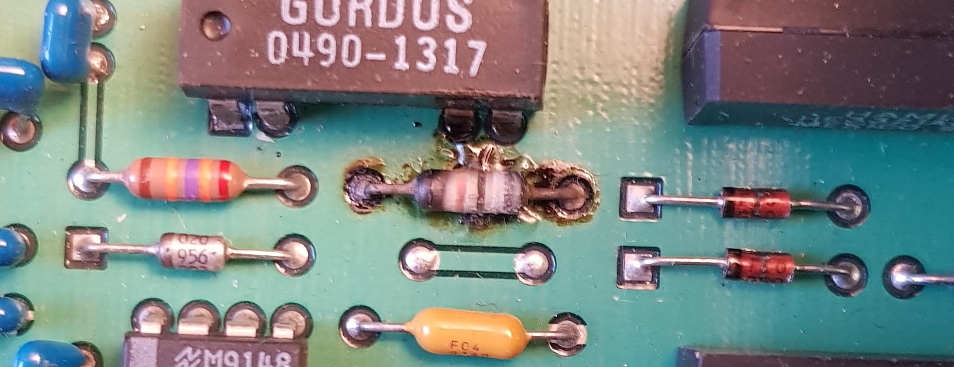
Looking at R113, which was burned, I couldn't really figure out what happened. Since that resistor cannot really be overloaded by DC from the input, I suspect either some botched repair, like accidentally shorting something or maybe some brutal high frequency input overload. But I'm not able to tell why these components failed. 

Nevertheless, I performed the adjustment steps in the service manual, since the input stage had been  repaired. All steps completed correctly, so I'm happy to have yet another nice universal counter after a quite challenging repair. One can never have enough frequency counters!


Sunday, October 3, 2021

Repair of an HP 5334B counter - Part 1 - first looks

Some time ago, I got an HP 5334B counter off eBay. It was advertised az not powering up and it had a best offer option. I like not powering up stuff, as usually they have some simple problems. It was missing the display cover, but since the unit had the OCXO option and based on the pictures I was able to confirm that the HP 10811 oven oscillator was there, I submitted an offer of about the third of what the OCXO is worth by itself. Somewhat to my surprise the offer was accepted and the counter was on its way to me.


Initial inspection has shown that there were no major parts missing and it indeed had the oven oscillator.


After making sure on the line voltage setting, I also confirmed that it did not power up, not even the standby led, which should indicate that the oven is powered up. So I checked the trivial stuff first. The fuse seemed to be good, but I always measure if it does not look obviously blown.


Hmmmm. That OL on the meter is sure makes me suspicious that the fuse is not as good as it looks. I got a replacement and look, it powers up. That sure is easy. Or maybe not, still need to test it.


In case you are wondering in the meantime I was able to get a front panel for a couple of bucks, complete with the display cover. The cover was installed, it simply pops into place and I now have a bunch of replacement switches for vintage HP equipment. It also had the plastic trim on the upper side of the front, so test equipment OCD was avoided this time, by not missing anything from the unit.

However, not all is nice. The trigger led for channel A is always lit and channel A does not work at all. B and C do. Fortunately for someone who repairs test equipment for fun, it was not simply a blown fuse.

So let's get the service manual and follow the signal path for the input. In this case, the gameplan is to simply follow along and see where the signal disappears. The input may have been blown by overvoltage or anything like that could have happened, so a systematic fault finding is the best way to go.

Connecting A and B with the Com key will make Channel B count the A input, but that does not help a lot, since the Common switch as very near to the front of Channel A, only the AC/DC coupling switch (relay) and the 50 ohm input terminating resistor is there. But, at least we know that those are good.

On the other hand I discovered that R113 is fried. So there was very likely some overload situation.


The only problem is that R113 is in Channel B, so this is not the cause of a faulty Channel A.

In the next part I'll go trough the testing of Channel A components.