Some time ago, I got an HP 5334B counter off eBay. It was advertised az not powering up and it had a best offer option. I like not powering up stuff, as usually they have some simple problems. It was missing the display cover, but since the unit had the OCXO option and based on the pictures I was able to confirm that the HP 10811 oven oscillator was there, I submitted an offer of about the third of what the OCXO is worth by itself. Somewhat to my surprise the offer was accepted and the counter was on its way to me.

Initial inspection has shown that there were no major parts missing and it indeed had the oven oscillator.

After making sure on the line voltage setting, I also confirmed that it did not power up, not even the standby led, which should indicate that the oven is powered up. So I checked the trivial stuff first. The fuse seemed to be good, but I always measure if it does not look obviously blown.

Hmmmm. That OL on the meter is sure makes me suspicious that the fuse is not as good as it looks. I got a replacement and look, it powers up. That sure is easy. Or maybe not, still need to test it.

In case you are wondering in the meantime I was able to get a front panel for a couple of bucks, complete with the display cover. The cover was installed, it simply pops into place and I now have a bunch of replacement switches for vintage HP equipment. It also had the plastic trim on the upper side of the front, so test equipment OCD was avoided this time, by not missing anything from the unit.
However, not all is nice. The trigger led for channel A is always lit and channel A does not work at all. B and C do. Fortunately for someone who repairs test equipment for fun, it was not simply a blown fuse.
So let's get the service manual and follow the signal path for the input. In this case, the gameplan is to simply follow along and see where the signal disappears. The input may have been blown by overvoltage or anything like that could have happened, so a systematic fault finding is the best way to go.
Connecting A and B with the Com key will make Channel B count the A input, but that does not help a lot, since the Common switch as very near to the front of Channel A, only the AC/DC coupling switch (relay) and the 50 ohm input terminating resistor is there. But, at least we know that those are good.
On the other hand I discovered that R113 is fried. So there was very likely some overload situation.
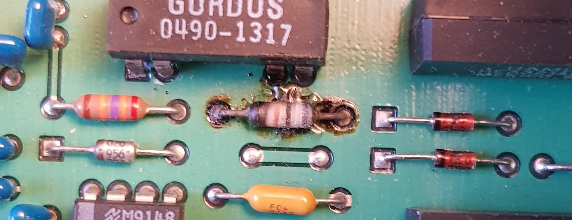
The only problem is that R113 is in Channel B, so this is not the cause of a faulty Channel A.
In the next part I'll go trough the testing of Channel A components.