Thursday, August 27, 2020

YAO - Yet Another OCXO for the HP 5316A counter

The HP 5316A is a nice little counter. Well, not so little, it is housed in a deep case, but certainly not a 5335A sized beast.

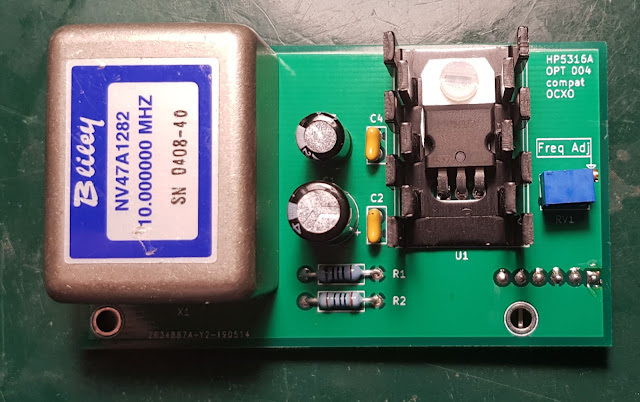
I have one which I originally built from two non working units sourced from eBay. It has Option 003, which is the 1.3GHz channel C, a useful option. However, it does not have a high stability timebase. Option 001 is the TCXO and Option 004 is the OCXO. It has neither, just a simple quartz oscillator. While it is not impossible to find the OCXO option on eBay, it is certainly not economical to do so due to its price. It usually costs way more than the base instrument itself. Furthermore, it is a bulky unit, with the power supply board and the oven being two separate units. I wouldn't even bother with it, as I already have plenty of counters with ovenized references and I have a GPSDO anyway. But, I had a Bliley 47A1282 OCXO laying around in my junk box. So why not use that to replicate Opt 004 and have a counter that can be used outside of the lab. 

I'm not the first one to venture into this project, there is a whole thread on EEVblog on this. I could have taken one of the designs there, but due to the different OCXOs, availability of parts, etc., it would have needed redesign anyway. So, why not start the design from scratch, it is a nice little project for those rainy evenings.

The requirements I set were fairly straightforward:

  • Use common parts, and of course use the OCXO I already have.
  • The design should be electronically compatible with the counter, and
  • it should also be mechanically compatible, including connectors, fastening and access for adjustment.

These are not hard to meet. The design is very simple. By looking at the service manual of the 5316A the connector pinout is available. Basically the only thing required besides the actual OCXO is a power supply. The counter provides around 7.5V standby voltage. However, the OCXO module is running on 5V. This is solved by a simple 5V low dropout regulator, I used a L4941BV. Especially during the warm up, the OCXO can consume up to 500mA, so to be on the safe side a small heatsink is required on the regulator.

Other than the supply, there are two additional components on the board. One is a 12 turn pot for the fine tuning of the frequency and the other is the 50ohm (R1 and R2) termination for the 10MHz out, as required by the datasheet of the OCXO.

The schematic was drafted in KiCAD.

KiCAD was also used for the  PCB design 

The PCB was designed to mount the same vertical way as the original oscillator boards, using the same L shaped brackets and right angle pin header. The tuning pot is placed in such a way, that it is accessible via the hole on the backpanel, so one can do closed cased adjustment for better thermal equilibrium. Although in practice, due to the long distance, it is quite fiddly to be able to access the very small screw on the pot.

I got the PCB manufactured by JLC PCB, they did a good job.


 After soldering all the components, verifying that the regulator is working as intended I installed the boards, which worked at first try.


I did successfully adjust it to my GPSDO, which is a good sign as it means the OCXO module is not outside its nominal frequency. (Of course that was verified in advance.)
There is the new Opt 004 in the top left corner of the picture, next to the HPIB interface boards.
So far it has been working fine, I will sometime check how much it drifts.


Monday, August 24, 2020

Completing Opt 004 on the 5342A

Continuing from Part 1
I got all the required components and based on the schematics and board layout in the service manual, I simply installed all of them. I was trying to make it look as original as I could, so I even used proper push on pins for the additional connection of wires (though I did not have gold plated ones, bummer), and in general, used parts that fitted well to the footprints on the board. 
This was quite simple. A handful of components to the A2 display board and a couple of wires from the backplane to the board. An hour later I had the finished board.
The new components are on the right. The DAC80-CCD-V chip is evident. There are the four TTL ICs next to the DAC to the left. Some resistors and trimmers on the upper right and the SMB connector for the output just below the DAC. The empty socket is for the connecting cable to the mainboard.
That is all for the display board.
Three wires are needed from the backplane to provide power (+- 15V) to the DAC and to provide the LDA signal for the CPU access. 

Also required a run of coax cable from the SMB socket to the BNC connector on the backside of the instrument (upmost BNC on the picture).


All components were installed, the wires connected and secured. Then I hooked up a multimeter to the DAC out, gave some signal to the 5342A to count and hit the DAC button. I got a voltage out which was about right. Promising start, so I did the adjustment procedure described in the service manual. Basically the offset and the gain pots had to be adjusted to get zero and 9.99V out for 000 and 999 counts at the specified digits. 
The video shows the somewhat useless demonstration of selecting the drifting Hz digits for DAC source. The voltage is accurate and sometimes it can be seen that the digits are probably entered sequentially into the DAC, the Fluke 87 is fast enough to do a measurement between the update of the most and least significant digit.
It is also good to know that the DAC will convert any digits to voltage, so if the unit is equipped with Opt 002 for RF level measurement, one can hit AMPL for the dBm display and then do a SHIFT-DAC-9 and the DAC output will provide the dBm level, though without the sign for negative values. But still, this could be useful
So to summarize, it is possible to retrofit Opt 004 to the HP 5342A counter. There is only one special part required, the DAC, but even that can be sourced easily. All other parts are common and readily available. 

Thursday, July 23, 2020

Adding Opt 001 and Opt 004 to the 5342A - Part 1

I have recently fixed an HP 5342A microwave frequency counter.
The unit  has options 002 (amplitude measurement which includes 003 extended dynamic range) and 011 (HPIB).
It is working fine, but this is when the Test Equipment OCD kicks in.
Still missing options 001 (OCXO) an. 004, the DAC output. How can I have an instrument without all the possible options?

Option 001 is easy. I have a 10544A OCXO waiting to be used, so out comes the standard TCXO and in goes the OCXO. Bit fiddly to have all the other cables arranged in the tight space, but simple.

Option 004 is not that straightforward. According to the manual, it requires a new display board. However, if you look closely at the current display board, there are some unpopulated footprints there.

The service manual actually has a photo of the Opt004 A2 board and there are schematics for it. 
So I studied them and found that indeed the PCB is the same, it just needs the following parts to be installed.

U14    74ls193 - counter
U15    74ls138 - demultiplexer
U20    74ls193 - counter
U21    74ls193 - counter
U23    DAC-80-CCD-V - DAC

R23    4k7 5% - resistor
R29    10k 5% - resistor
R30    180k 5% - resistor
R31    180k 5% - resistor
R32    270k 5% - resistor
R33    270k 5% - resistor
R34    3k9 5% - resistor

R25    100k - trimmer pot
R27    100k - trimmer pot

C9    0.01uF/100V - ceramic capacitor

J2    SMB socket

Some pins and wires for connection, including a coax pigtail with SMB connector to connect the DAC out BNC at the back, which is already there.

C12, C14 and C15 are deleted according to the manual, so these will be left unpopulated
With the exception of the DAC, these are all very common and readily available parts. As luck would have it, I have one such DAC from some old instrument PCB, so of course I have to implement this option. But even If I did not have it, the DAC available on eBay for a reasonable price.

So let's go, get all the parts and see how it works. Continued in Part 2

Wednesday, July 22, 2020

Fixing an HP 5342A microwave counter. The anticlimactic last part.

In Part 3 I stopped while waiting for parts to make the adapter board for the ROM. Well, I'm still waiting for these, looks like the Covid situation doesn't make it simple.
However, while casually browsing eBay, I found a seller in Israel selling a CPU board for an insanely high price. However there was a "Make an Offer" opportunity, so I sent in an similarly insane, but low offer. I was astonished when a couple of hours later eBay popped up the "Offer accepted, please pay now" message. Sometimes it pays to be aggressive in bargaining.
So two weeks later this came in the mail.

This is actually a newer version of the board, part no.: 05342-60072, but the only difference seems to be the use of one larger ROM instead of the 3 2k parts.
I plugged the board in, and magically everything came to life. The counter was working fine, option 002 measured the dBm's etc. So after much fun with debugging and researching I was able to take the easy way and a simple board swap fixed it. Isn't it cheating?


Wednesday, June 17, 2020

Fixing an HP 5342A microwave counter. Part 3.

Part 3. is going to be short, as (spoiler!) I am waiting for parts.
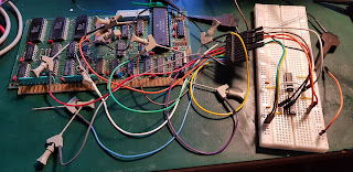
So in Part 2. I said I was coming to the conclusion that it may be ROM problem. Based on the extender card, I built the logic on a breadboard to have the ROM select signals to be able to do a signature analysis.

Well, it turned out that U7 is not corrupted, but completely dead. Looking at its outputs when selected, all outputs stayed low.


The other two ROM ICs had the correct signature so, they can be considered good.

How to proceed? Since I did not find any firmware binary online, I posted the question on the HP group and immediately got the binaries. Very helpful people there, I am absolutely grateful. I also got an offer for a working CPU board, that is my plan B. Simply swapping boards is cheating when reviving vintage instruments :-)
I was pointed to Retro Innovations' adapter to be able to use a 27xx EPROM in place of a 23xx ROM (which is the one in this instrument). It is a very simple adapter, but since it had a very reasonable price I ordered one. It was just not worth bothering with designing the PCB and having it fabricated. I also had a couple of 2716 EPROMS, which I did erase, but for some unknown reason, none of them became blank, even though other EPROMS did, as I used the opportunity to erase all my junkbox EPROMS. Hence I have ordered a coupe of 2716s from eBay, I'm curious to find if they are fakes or not. If they are, Ill use some other higher capacity EPROM, they should work as well.
So this is where it stands now, once I get the adapter I'll see if this makes it work or not. I will continue in part 4.

Wednesday, May 27, 2020

Fixing an HP 5342A microwave counter. Part 2.

Continuing from Part 1.
I got a new CPU, this time in a plastic package, not a shiny ceramic with golden cap, but should be good otherwise. The questions are: a) was the original CPU faulty and b) did a new one fix the instrument?
And the answers are Yes and No.
I installed the replacement CPU and tested. Exactly the same result, the instrument is frozen with garbled front panel. However, I don't have the glitches on the address lines. While apparently this did not affect anything, it still indicates that something is at least marginal with the old CPU.
How to proceed? At one time HP was very keen on signature analysis, which can indeed help in some cases at least by confirming that the tested part of the circuit works.
I am now beginning to suspect that one of the ROMs may be bad, which would suck, but first I must make sure that I can test is properly.
Why do I think that it may be ROM problem and not, for example front panel? Using the test switches on the CPU board, I can disable individual bits of the data bus. Obviously the CPU would be running a nonsense random program in this case, but for example disabling bit 3 will make it run in some loop, where the front panel display are changing. Obviously, the strobe signal to write into the panel is activated randomly and whatever random data is there will get written into the display.
At least this is what I think, it is still possible that the front panel is faulty and I'm chasing a red herring on the CPU board. But first I want to confirm whether the CPU board is good or not.
For this there are extensive signature tests in the service manual. First in free run (NOP) mode, which tests all the address lines and all the various device select signals which actually covers a large part of the login on the board. This can indeed be done by powering up the CPU board outside the instrument.
So, let dig out the trusty old Sony/Tektronix 308 Data Analyzer, which can do signature analysis and some rudimentary serial and parallel logic analysis and looks like a cute little oscilloscope. And for some insane reason it is usually cheaper on eBay than a HP signature analyzer which can only do signature analysis.
Well, all signatures check out OK. So at least these parts are good.
The next step would be to do a signature test on the ROMs. And that is where I stop now, as it does require the CPU extender card which contains additional logic to provide the start and stop signals for the ROM signature test. I don't have this card, but a kind gentleman on the Vintage HP equipment group pointed out that the schematics for the extender is in fact in the service manual.
It is not complicated, so I'm now tempted to put together one on a breadboard and be able to do the analysis as I really want to confirm if the ROMs work or not.
So I'll continue in Part 3.

Wednesday, May 20, 2020

Fixing an HP 5342A microwave counter. Part 1.

While browsing eBay I came across a HP5342A microwave frequency counter for a very attractive price. Normally, it is a very risky business to buy this instrument, as most of the units on eBay do not work. Usually the input mixer is blown due to overload and that component is unobtainable, unless you have a parts mule with a good mixer. However, in this case the instrument was shown booting with a garbled display and unresponsive keyboard. The seller said that it had been used before. We all know that nothing can be assumed true in eBay item descriptions, but I felt it was still worth trying.
The not working front panel could mean a lot of things, a broken front panel, a broken PSU, a broken CPU but those can all be fixed with a high probability. So I took the chance and won the auction.

Well, the description was correct, It sure did not work. The display has invalid characters and no response from the keyboard.
The display is deterministic, I get the same hieroglyphs on every boot. 

So let's check the usual suspects. I reseated all the cards. Boy, there are a lot of screws to remove to open the internal shielding! The supply voltages and ripple all were within specs. So, the problem is more complex.
Let's start with figuring if it is the front panel or something else. The display has its own memory and oscillator for multiplexing and scanning the keys. The CPU updates the keyboard by strobing the HDSPWRT line which updates the display RAM. The keys generate interrupts and the CPU can read which key was pressed.
Let's look at these signals. Unfortunately all the cards are in a shielded compartment, so it is impossible to access them to probe. The proper way would be to use extender boards. There is a set for the various cards and for the CPU board there is a special one (HP part no.:05342-60036) which is not a simple feed-through board, but has additional switches, logic and test points. Some simple extenders are available on eBay, but they cost more than what I paid for the whole unit. The CPU extender, I have not seen even a reference of anyone having and selling one.
However, not all is lost. Most of the signals are available on the bottom side of the motherboards and also on the back CPU connector, which is supposed to be used in combination with the 5344A unit.
While HP gets some points deducted for the extender boards, kudos to them for extensive silkscreen printing on the motherboard for the various signal names.
So, I looked at the HDSPWRT signal and it was not changing, indicating that probably there is some problem with the CPU unit.
Next step, debugging the CPU unit. I first pulled boards that may affect the CPU, the counter assembly and the Opt 002 card, no change. The service manual actually calls for a signature analyzer, which I do have in the form of a Tektronix/Sony 308 Data Analyzer, but first I need to confirm if the CPU extender is needed for it or not as the manual instructs some switch setting on the riser for the signature analysis. So first let's see what we find without it.
The CPU card has switches to put the CPU into NOP mode, where the data bus is forced to provide the opcode for a one byte instruction. This is usually the NOP (no operation) instruction, but in this case it is the CLR B (clear accumulator B) instruction. Nevertheless, the result is the same the CPU should be cycling trough the whole address range while executing this instruction. One can then put a scope or LA on the address lines and see them counting up, with every higher order bit toggling with half the frequency of the one before.
From A0 to A7 this worked very nice. However, from A8 to A15 I have seen some glitches. With some tweaking on the trigger I was able to capture one of this glitch. Looks like A8 is glitching and that affects all higher order bits of course.
Oops, this looks ugly. Something is definitely wrong.
Test 1. Remove the CPU and with a cut up socket, isolate all signals that are not required for the test and run again. All address lines are now unconnected, so it is not something pulling them high periodically.
Same result. I double checked all pins if I see any correlation to these glitches, but no. Power is rock solid, so are all other pins. I actually removed the CPU card and provided power and 1MHz clock externally. The fi1 and fi2 clock phases are generated in the board from the clock signal, so the whole CPU card can be made running outside the instrument.
So could this be a faulty CPU?
Test 2. Remove the CPU, put it into a proto board, use my Tek AWG2021 to produce the two phase clock.
Wow. There are no glitches. What could make this difference? I have examined the clock closely on the 5342A CPU board, it it in spec, though it has much less separation of the the two phase, but it is still well within spec for the 6800. I see no other difference, except maybe some load on some of the pins. Puzzling.
So this is where I stand now. I'm actually getting a new CPU for a test, just have to wait a couple of days during this virus lock-down times. That should close out or confirm if it is the CPU. Then we'll see where to go forward.
Stay tuned, the result of the CPU replacement will come in Part 2.