The HP 5316A is a nice little counter. Well, not so little, it is housed in a deep case, but certainly not a 5335A sized beast.
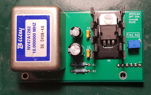
I have one which I originally built from two non working units sourced from eBay. It has Option 003, which is the 1.3GHz channel C, a useful option. However, it does not have a high stability timebase. Option 001 is the TCXO and Option 004 is the OCXO. It has neither, just a simple quartz oscillator. While it is not impossible to find the OCXO option on eBay, it is certainly not economical to do so due to its price. It usually costs way more than the base instrument itself. Furthermore, it is a bulky unit, with the power supply board and the oven being two separate units. I wouldn't even bother with it, as I already have plenty of counters with ovenized references and I have a GPSDO anyway. But, I had a Bliley 47A1282 OCXO laying around in my junk box. So why not use that to replicate Opt 004 and have a counter that can be used outside of the lab.
I'm not the first one to venture into this project, there is a whole thread on EEVblog on this. I could have taken one of the designs there, but due to the different OCXOs, availability of parts, etc., it would have needed redesign anyway. So, why not start the design from scratch, it is a nice little project for those rainy evenings.
The requirements I set were fairly straightforward:
- Use common parts, and of course use the OCXO I already have.
- The design should be electronically compatible with the counter, and
- it should also be mechanically compatible, including connectors, fastening and access for adjustment.
These are not hard to meet. The design is very simple. By looking at the service manual of the 5316A the connector pinout is available. Basically the only thing required besides the actual OCXO is a power supply. The counter provides around 7.5V standby voltage. However, the OCXO module is running on 5V. This is solved by a simple 5V low dropout regulator, I used a L4941BV. Especially during the warm up, the OCXO can consume up to 500mA, so to be on the safe side a small heatsink is required on the regulator.
Other than the supply, there are two additional components on the board. One is a 12 turn pot for the fine tuning of the frequency and the other is the 50ohm (R1 and R2) termination for the 10MHz out, as required by the datasheet of the OCXO.
The schematic was drafted in KiCAD.
The PCB was designed to mount the same vertical way as the original oscillator boards, using the same L shaped brackets and right angle pin header. The tuning pot is placed in such a way, that it is accessible via the hole on the backpanel, so one can do closed cased adjustment for better thermal equilibrium. Although in practice, due to the long distance, it is quite fiddly to be able to access the very small screw on the pot.
I got the PCB manufactured by JLC PCB, they did a good job.


No comments:
Post a Comment