Tuesday, April 20, 2021

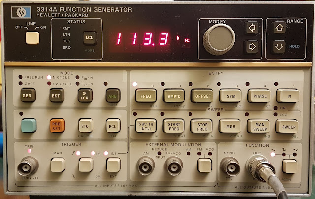
Fixing an HP 3314A function generator - repair complete!

Wrapping up from Part 2

I managed to source a CA3082 locally, so there is no need for any workaround. I popped it in, and it worked.


I had a problem with one of the reed relays, but this time it was not on the driver side, but on the actual reed contact. It wouldn't work however I exercised it by quick switching. By luck, I had a handful of reed contacts with the same size, so I snipped the old one out, it was spot welded and soldered in the new one. Carefully, they are fragile. I say this from experience.

 Fortunately both leads could be soldered well, it would have been hard to weld them again. 

I went trough the adjustment section of the manual, got everything in spec. Now I have proudly resurrected a vintage 3314A from a quite bad repair attempt by a previous owner. 

It is a nice and still quite capable instrument.


Tuesday, April 13, 2021

Fixing an HP 3314A function generator - Part 2.

Continuing with the repair of the HP 3314A function generator that was "repaired" by a previous owner. I left off at the decision of checking everything that was done to it.

First I had to clean up. 5 of the 6 EPROM adapter boards were soldered into the instrument and for some unknown reason 1 was in a socket. I started beeping out the connection between the EPROMs for the data and address lines, and sure enough, found several where there were no connection. Not very surprising, given what I have seen with the 74S74 IC in the clock generator circuit. Also, some of the adapter boards were bad, there was no connection between some of the pins, there were cold solder joins there.

Very carefully I started removing the adapters. Even though HP made quite sturdy PCBs, I didn't want to risk any more damage, so I snipped the pins of the adapters and removed them one by one. I also removed the two 74ls373, they are the ones with the two jumpers next to them. You can see the solder blobs at their ends near to the EPROMs. That is where their pins were snipped and soldered from above, presumably to fit after the adapter boards were already put in.

Once everything was removed, I was already able to see four broken traces under U209, the one in the socket. Those were fixed with scraping off the solder mask and soldering twin wires there.

Then I checked for continuity for every pad related to the ROMs and installed high quality sockets and replaced the 2 74ls373. All this took quite some time, but was well worth the effort as at the end I had a nice board.

I again double checked continuity to the sockets and proceeded with getting the EPROMs fixed.

Next, I turned my attention to the adapter boards. My initial idea was to scrap the 6 EPROMs and just use one with a 74ls148 priority encoder figuring out the additional address lines from the 6 chip select signals. But to make it nice it needed some PCB, and work, and then I also realized I actually had 3 of the same (well, nearly same, they were blue, and a bit different layout) adapter boards from an earlier project, so I actually only had to clean up three of the old ones. So I went with tidying up those boards, as the previous owner even got those wrong, instead of using the proper jumper places he used bodge wires to configure it. After some tedious work with the solder sucker and the iron, I got all six EPROMs ready for action.

Plugged them in and did again a quick check that everything is in place and turned the instrument on. It started the countdown and then did the calibration sequence without problem. Honestly I wasn't expecting that, I was prepared to see a bunch of calibration errors at best.

Halleluja! But does it play Halleluja? No! There is no output. There is output from the sync, but nothing from the signal. 

Ok, don't panic, just think. If the calibration sequence is successful, then there must be a signal with proper amplitude and frequency where the calibration signal is picked off. Looking at the schematics, this is done nearly at the very end, after the output amplifier, but before the output attenuator.  I quickly verified this with a scope. Looks like the signal is lost somewhere at the reed relays. So the main suspect now is the relays themselves or the drivers of the relay coils.

The relays are controlled by a latch which in turn controls a CA3082 transistor array. The latch seems to be good, but the voltages on some of the outputs of the array were strange. As a quick test I piggybacked some random NPN transistor on one of these outputs, and surprise surprise, the corresponding relay came to life. 

So the CA3082 seems to be a fault. This is an obsolete part, not too easy to get. Of course I made a purchase on eBay for some cheap solution, I'm pretty much certain that it will be fake, but let's take some chances. As plan B I also designed a small PCB with surface mount transistors as a pin compatible replacement. 
So right now I'm waiting for either a working replacement or the PCB. This will take a couple of weeks probably. Hopefully this will fix the instrument. I'll write a Part 3. of this post once this happens.


Monday, April 12, 2021

Fixing an HP 3314A function generator - Part 1

 Some time ago I scored a nice looking HP 3314A function generator of eBay. It was advertised as not powering up, so there was a chance that there is some simple problem. I took a chance and was able to get it for cheap.

When it arrived, I took a closer look. I immediately noticed something rattling inside, and this is what I saw after I had opened it up.


One of the EPROMs was loose and bouncing around inside the case. I first though that it may be that simple, but a closer look provided a much gloomier forecast. The EPROMs were infact in a small adapter boards, so someone has been here before. The adapter boards by themselves are not a problem, the Mostek ROMs in these units are known to fail and can quite easily be replaced by 2764 EPROMs, using an adapter to fix the pinout differences.

However, the soldering job on these adapters were horrible. There were large blobs of solder everywhere, sockets being melted, bodge wires going over and under sockets, etc. So I was not too optimistic, when I reseated the EPROM. Especially that I noticed that two EPROMs had some of their pins crushed when they were apparently misaligned during insertion. See pin 19 of U208 in the above picture. Someone was very careless in the past. I fixed those, fortunately without breaking the bent pins.

Flipping the power switch, the fan starts, but no sign of life. Not even the ROM checksum test.

OK, lets dig deeper. First the trivial stuff. Power rails were good, all within spec with voltage and ripple. Next, check the CPU activity. Ooops! Out of the two clock signals, only one is there, that can't be good.

Let's go and follow the signal path for the clock. The two-phase clock is derived from the master crystal oscillator and I very quickly discovered that  the problem is at a 74S74 IC. Interestingly enough, this IC is in a socket, so looks like someone replaced it at some point of time in the past. Hmmm. Anyway, because of the socket, I was quickly able to replace it, without any effect.

It was time to examine the board more carefully. I removed it from the clever fold out metal sheet, and this is what I saw.

The previous owner had butchered the PCB for the U201, the 74s74. (I'm not sure what he was using, a flamethrower and some blacksmith tools maybe.) Anyway a trace was broken at one of the pins and replaced with a jumper wire. Which became pinched under one of the screws holding down the board and got grounded. No wonder the clock was a flat-liner. I guess this worked for some time while the insulation got chewed up, or the screw was finally tightened, so this is why the previous repairer did not notice it.

I redid the soldering and patched the trace, so got rid of the long wire. Immediately I had nice clock, but still no sign of life. 

Next step is Signature Analysis (SA). Some like it, some don't, but HP was very keen on having this debug function in their CPU driven instruments. In my experience it can be a very useful and easy to use tool for some of the troubleshooting steps. I hooked up my Sony-Tektronix 308 Data Analyzer to go trough the  SA tests. I still had a feeling that the ROMs would be the problems, but let's exclude everything else first. 

The first test is the freerun test, when the CPU is fed a harmless instruction at every memory read to just sweep trough all the memory addresses. So we are basically supposed to see A15-A0 count up to cover the whole 64k memory range. With the SA this will also test most of the memory decoder functions. 

The first attempt wasn't successful. The signatures on the CPU pins checked out fine, but two of the address lines after the 74LS373 latches were bad. I looked at then with a scope and looked like the two lines were shorted. Obviously the prime suspects were the 373s. Even more so, as there were huge blobs of solder on some of the pins on the component side. Looks like that someone wanted to replace them after the EPROM adapter cards were soldered in and they prevented from lifting the 373 out of the PCB and also inserting the new one. So he cut the offending pins flush with the bottom of the IC and then soldered them in from above. Which of course resulted in a short. Then probably at this time he gave up, and put the unit on eBay, where I got it.

I fixed the short, and then the freerun SA tests finally completed successfully. But still no sign of operation. Next came the ROM SA tests, which basically do a checksum like test on the EPROMs. 

3 out of 6 ROMs were good, the rest did not give a stable reading. But by wiggling the ROMS, sometimes I got a good result. Obviously the excellent soldering skills of the previous owner struck again.

At this point I decided to remove all the ROMs, check the EPROM contents, check the adapter cards and check the PCB under the ROMs, as I felt that if the previous owner did such a massacre with a 14 pin IC, then a 24 pin would not be any better. And boy,  I was right.

Stay tuned for the next part.