Thursday, August 27, 2020

YAO - Yet Another OCXO for the HP 5316A counter

The HP 5316A is a nice little counter. Well, not so little, it is housed in a deep case, but certainly not a 5335A sized beast.

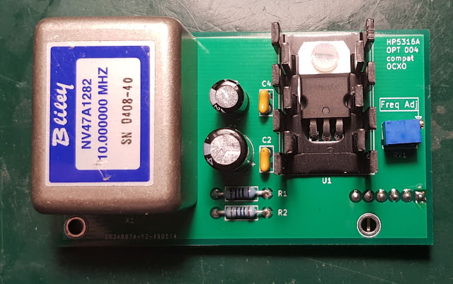
I have one which I originally built from two non working units sourced from eBay. It has Option 003, which is the 1.3GHz channel C, a useful option. However, it does not have a high stability timebase. Option 001 is the TCXO and Option 004 is the OCXO. It has neither, just a simple quartz oscillator. While it is not impossible to find the OCXO option on eBay, it is certainly not economical to do so due to its price. It usually costs way more than the base instrument itself. Furthermore, it is a bulky unit, with the power supply board and the oven being two separate units. I wouldn't even bother with it, as I already have plenty of counters with ovenized references and I have a GPSDO anyway. But, I had a Bliley 47A1282 OCXO laying around in my junk box. So why not use that to replicate Opt 004 and have a counter that can be used outside of the lab. 

I'm not the first one to venture into this project, there is a whole thread on EEVblog on this. I could have taken one of the designs there, but due to the different OCXOs, availability of parts, etc., it would have needed redesign anyway. So, why not start the design from scratch, it is a nice little project for those rainy evenings.

The requirements I set were fairly straightforward:

  • Use common parts, and of course use the OCXO I already have.
  • The design should be electronically compatible with the counter, and
  • it should also be mechanically compatible, including connectors, fastening and access for adjustment.

These are not hard to meet. The design is very simple. By looking at the service manual of the 5316A the connector pinout is available. Basically the only thing required besides the actual OCXO is a power supply. The counter provides around 7.5V standby voltage. However, the OCXO module is running on 5V. This is solved by a simple 5V low dropout regulator, I used a L4941BV. Especially during the warm up, the OCXO can consume up to 500mA, so to be on the safe side a small heatsink is required on the regulator.

Other than the supply, there are two additional components on the board. One is a 12 turn pot for the fine tuning of the frequency and the other is the 50ohm (R1 and R2) termination for the 10MHz out, as required by the datasheet of the OCXO.

The schematic was drafted in KiCAD.

KiCAD was also used for the  PCB design 

The PCB was designed to mount the same vertical way as the original oscillator boards, using the same L shaped brackets and right angle pin header. The tuning pot is placed in such a way, that it is accessible via the hole on the backpanel, so one can do closed cased adjustment for better thermal equilibrium. Although in practice, due to the long distance, it is quite fiddly to be able to access the very small screw on the pot.

I got the PCB manufactured by JLC PCB, they did a good job.


 After soldering all the components, verifying that the regulator is working as intended I installed the boards, which worked at first try.


I did successfully adjust it to my GPSDO, which is a good sign as it means the OCXO module is not outside its nominal frequency. (Of course that was verified in advance.)
There is the new Opt 004 in the top left corner of the picture, next to the HPIB interface boards.
So far it has been working fine, I will sometime check how much it drifts.


Monday, August 24, 2020

Completing Opt 004 on the 5342A

Continuing from Part 1
I got all the required components and based on the schematics and board layout in the service manual, I simply installed all of them. I was trying to make it look as original as I could, so I even used proper push on pins for the additional connection of wires (though I did not have gold plated ones, bummer), and in general, used parts that fitted well to the footprints on the board. 
This was quite simple. A handful of components to the A2 display board and a couple of wires from the backplane to the board. An hour later I had the finished board.
The new components are on the right. The DAC80-CCD-V chip is evident. There are the four TTL ICs next to the DAC to the left. Some resistors and trimmers on the upper right and the SMB connector for the output just below the DAC. The empty socket is for the connecting cable to the mainboard.
That is all for the display board.
Three wires are needed from the backplane to provide power (+- 15V) to the DAC and to provide the LDA signal for the CPU access. 

Also required a run of coax cable from the SMB socket to the BNC connector on the backside of the instrument (upmost BNC on the picture).


All components were installed, the wires connected and secured. Then I hooked up a multimeter to the DAC out, gave some signal to the 5342A to count and hit the DAC button. I got a voltage out which was about right. Promising start, so I did the adjustment procedure described in the service manual. Basically the offset and the gain pots had to be adjusted to get zero and 9.99V out for 000 and 999 counts at the specified digits. 
The video shows the somewhat useless demonstration of selecting the drifting Hz digits for DAC source. The voltage is accurate and sometimes it can be seen that the digits are probably entered sequentially into the DAC, the Fluke 87 is fast enough to do a measurement between the update of the most and least significant digit.
It is also good to know that the DAC will convert any digits to voltage, so if the unit is equipped with Opt 002 for RF level measurement, one can hit AMPL for the dBm display and then do a SHIFT-DAC-9 and the DAC output will provide the dBm level, though without the sign for negative values. But still, this could be useful
So to summarize, it is possible to retrofit Opt 004 to the HP 5342A counter. There is only one special part required, the DAC, but even that can be sourced easily. All other parts are common and readily available.